Chapter 2 · Independent study · Grades 11–12, May to Jun 2026

PLE-SBS

Pre-Launch Emergency: the Slidewire Basket System. A way down from a fuelled rocket for the crew and the close-out team, sized for any launch pad, and my add-on to the existing egress system: one wire, a switch yard and a bay for every pod.

PLE-SBS · Slidewire crew-escape study, paper and simulator · May to Jun 2026 · Paper dated 10 June 2026

In the hours before a crewed launch, astronauts and close-out technicians work 40 to 115 m above a fully fuelled rocket. If something goes wrong they need a way down that is faster than the lifts, works with the power off and keeps working in strong wind. NASA's slidewire baskets do this, but each has been engineered for one pad.

PLE-SBS is a slidewire basket system and a method for sizing one at any pad. It combines a hazard model that turns any rocket's propellant into a safe distance, a taut-cable model in which every pod's weight changes the slope under every other pod, and a Monte Carlo evacuation simulator, all in one dependency-free physics file with sixteen unit tests. Without tuning, it reproduces the Shuttle-era baskets' reported top speed: 24.0 m/s predicted, about 24.6 m/s reported.

The worked example is a generic 42 m pad with nine people to clear at danger level 4. Five design iterations, each run deterministically, at both wind corners and 1,000 times in Monte Carlo, took the design from a copy of the Artemis layout that failed 93% of runs to one that fails none.

Mentor and guide
Mrs. Abitha Peter, Class 12 Physics teacher
Paper
PLE-SBS.pdf, 10 June 2026, seven pages
Simulator
adithyakesan.com/ple_sbs/: any rocket on any pad, a single dock or a switch yard, a net or a chain bed, a failed brake, the Monte Carlo and the bill of materials
Code
github.com/AdithyaKesanJayakanth/PLE-SBS
Scale model
1:50, print-only: 22 printed parts and 1.5 mm wire rope, with the switch yard's self-indexing points and three bays; timed runs pending
Also
An A0 poster and a one-minute narrated video, in the repository
162 s

The 95th-percentile time until everyone is safe for the worked example: 42 m pad, nine people, danger level 4, 1,000 Monte Carlo runs, no failures. The first design, a copy of the Artemis layout on this low pad, gave 231 s with 93% of runs failing: from 42 m a 400 m wire ends almost flat, and no passive brake setting satisfies both wind corners. Geometry fixed it, a shorter, steeper wire into a shallow pit; then a bunker instead of a vehicle; then the human factors.
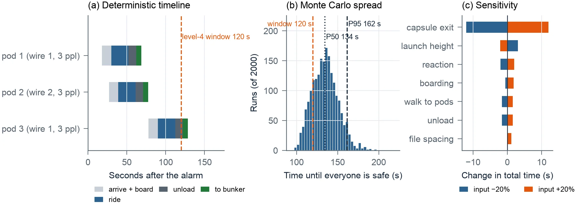
Three panels: a deterministic timeline of three pods against a 120 second window; a Monte Carlo histogram of time until everyone is safe with P50 134 s and P95 162 s; and a sensitivity bar chart in which capsule exit time dominates.
Fig. 1Design D4 on the worked example: deterministic timeline, Monte Carlo spread over 2,000 runs (P50 134 s, P95 162 s) and sensitivity. The 120 s level-4 window is not met, and the remaining seconds are human: capsule exit alone moves the total by ±12 s, more than every hardware parameter combined.
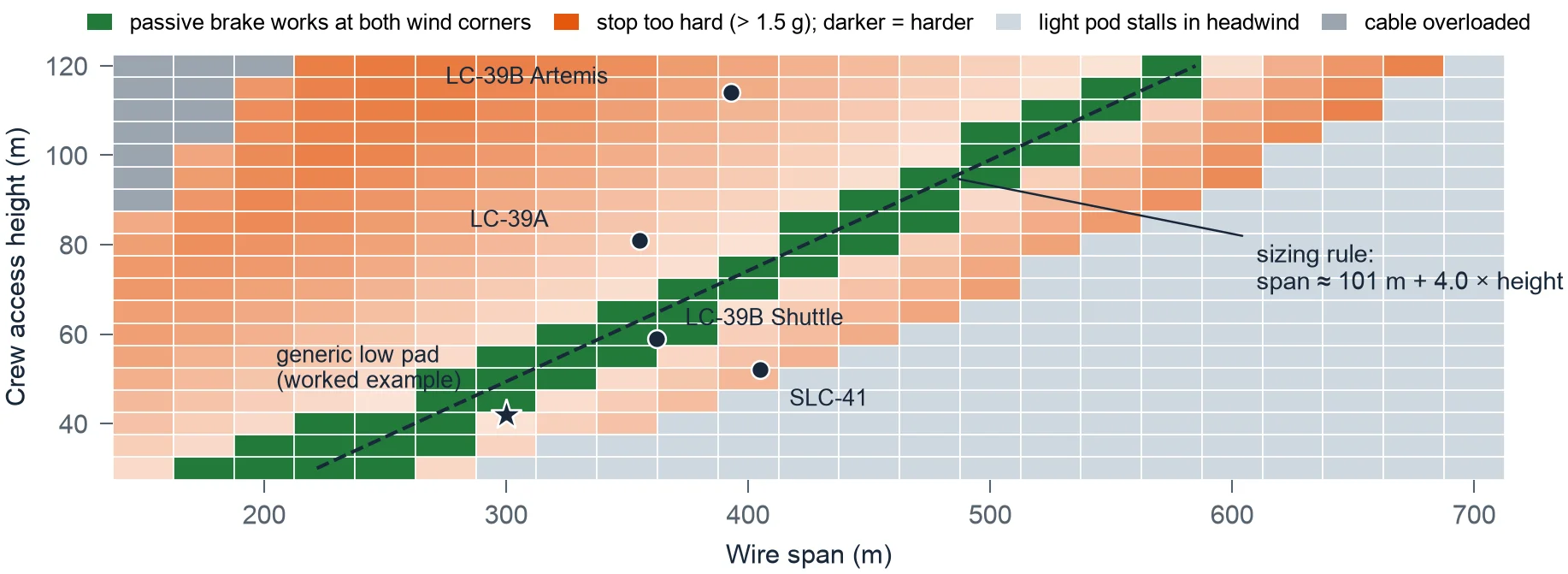
Map of crew access height against wire span, coloured by whether a passive brake works at both wind corners: a narrow green diagonal band with a fitted line, span about 101 m plus 4 times height; dots for existing NASA pads and a star for the worked example.
Fig. 2Passive-brake sizing map for any pad. Each cell is checked at both wind corners; green cells meet the wind, deceleration and no-stall requirements. Dots mark existing pads; the star is the worked example.

The central finding is general. A passive magnetic brake strong enough to stop a full pod in a tailwind can strand a lightly loaded pod in a headwind, because its force grows with speed and a light pod is braked harder. Passive braking therefore works only in a narrow diagonal band of geometry: for crew access heights of 30 to 120 m, the span should be about 100 m + 4 × the height.

The existing pads sit where their braking choices predict: the Shuttle pad on the band, with its catch nets and drag chains; the Artemis tower on the steep side, where it uses magnetic brakes along the line; SLC-41 on the flat side, where the riders control their own brakes.

8 s

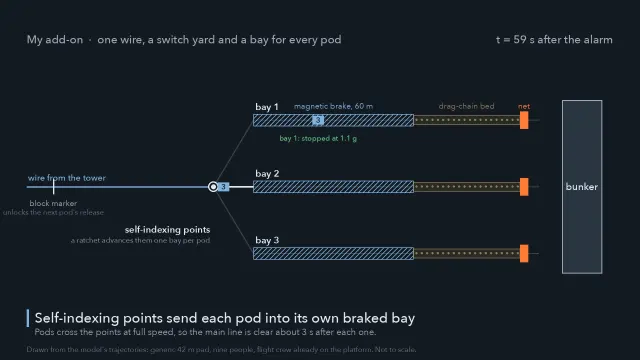
Between pods on one wire with the switch yard, against 37 s with a single dock. My add-on moves the braking off the shared wire. At the terminus the rope hands each trolley onto a ground rail, and self-indexing points, a railway turnout advanced one position by a ratchet that each passing pod trips, send pod 1 to bay 1, pod 2 to bay 2, and so on. Each bay has its own 60 m magnetic brake, drag-chain bed and net. The release lever is interlocked by a block marker 60 m down the wire, so if the pod ahead ever stalls the next stays at the platform. Nothing needs power.
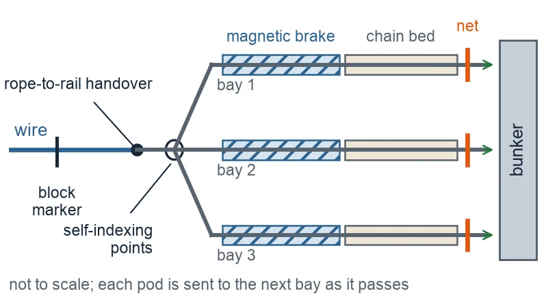
Plan diagram: the wire passes a block marker to a rope-to-rail handover and self-indexing points; three bays fan out, each with a hatched magnetic brake, a chain bed and a net, ending at the bunker.
Fig. 3D5 receiving end in plan: the wire hands each pod to a ground rail, and self-indexing points send each pod into its own bay with a magnetic brake, a drag-chain bed and a backup net, beside the bunker. Not to scale.
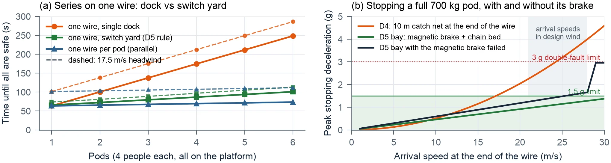
Left: time until all are safe against the number of pods on one wire, rising steeply for a single dock and staying flat for the switch yard and for one wire per pod. Right: peak stopping deceleration against arrival speed, the catch net rising past 3 g while the bay with a failed brake stays near 1.5 g.
Fig. 4(a) Time until everyone is safe as pods are added: one wire with a single dock, one wire with a switch yard, and one wire per pod; dashed lines are a 17.5 m/s headwind. (b) Peak stopping deceleration for a full pod: a catch net at the end of the wire (D4) against a switch-yard bay with its magnetic brake working and failed (D5).
113 s

24 people in six pods on one wire with the switch yard, in a design headwind: 286 s with a single dock, 111 s with six separate wires.

1.4 g

a full pod whose magnetic brake has failed, stopped in its bay's drag-chain bed (1.76 g with a tailwind). The catch net of D4 gave 3.8 g, above the 3 g double-fault limit.

5.9

safety factor of the 36 mm galvanised steel rope on breaking strength. Steel keeps about half its strength near 500 °C; polymer ropes melt at 145 to 260 °C.

24.0 m/s

Peak pod speed predicted for the Shuttle-era LC-39B baskets with no tuning, against about 55 mph (24.6 m/s) reported: within 3%. The same model says a tall tower needs magnetic braking over a large part of the descent, not only at the end, which is what the Artemis system does.
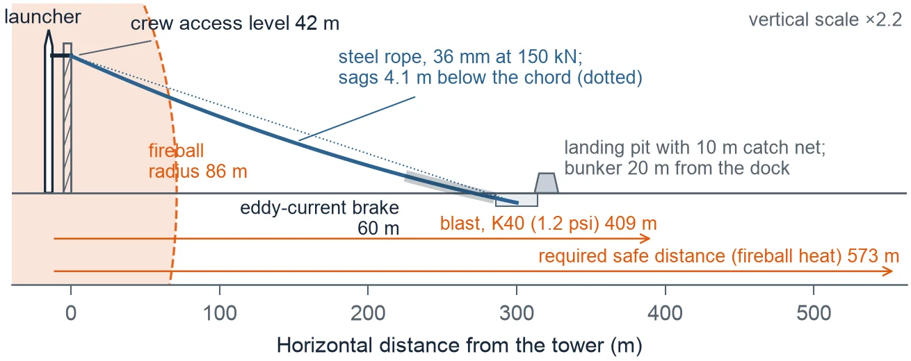
Side elevation of the worked example: launcher and tower with the crew access level at 42 m, the sagging steel rope to a landing pit 300 m away with a 60 m eddy-current brake, the fireball radius of 86 m, and the blast and fireball-heat safe distances at 409 and 573 m.
Fig. 5The worked example, drawn from the model: the rope's real sagged profile from the 42 m crew access level into a 3 m landing pit 300 m away, the fireball to scale, the blast and heat distances. Vertical scale × 2.2. Every safe distance exceeds any practical wire, so a protected terminus is part of the system.
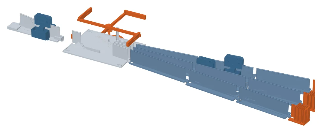
Render of the 1:50 printed parts laid out in a line: start gates with pods, the handover ramp and turnout with its star and cam, and three long bays with brake combs, chain beds and bumpers.
Fig. 6The print-only 1:50 model, rendered from its part files: handover ramp, turnout with the self-indexing points (tongue, cam and star), three bays with brake comb, chain bed and bumper, and three pods. Froude scaling makes a 3 s model run about 21 s full size.

All results are model predictions from public data and stated assumptions, not a certified safety analysis. The reference launcher and pad are generic; the danger levels and the capsule exit time are my estimates; debris, basket sway, rope stretch and the loss of eddy-current force at high speed are not modelled.

The scale model's pictures are renders of the part files. The timed runs that fit rolling resistance and drag area to measurement, through the simulator's scale-model tab, are the next step.

Where it came from, and how it was built

In September 2025 I designed roller-coaster tracks around the limits of the human body, for a CBSE state-level modelling competition: the thrill and the limit turned out to be the same number, and a track is a machine for giving people forces safely. I presented that model at ISRO in March 2026, and the scientists there raised a different question: a crew works a hundred metres up a tower beside a fuelled rocket; if the alarm sounds, how do they get down? PLE-SBS is the answer, carried from the hazard model to a simulator, a seven-page paper and a 1:50 model printed on a Bambu Lab P1S.
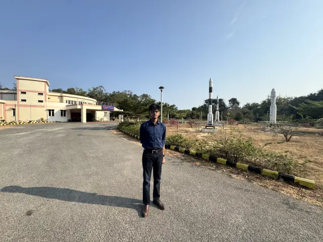
Adithya on the road through Satish Dhawan Space Centre with a launch vehicle model behind
Sriharikota, March 2026. Two days at the launch centre; the problem was suggested here.
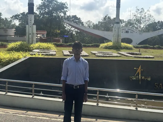
Adithya standing in front of the space centre's memorial garden
The pads. The older and the newer launch pad, and the question of the crew's way down.
Still from the PLE-SBS film: the simulator's side view of the pad, the wire and the pods
The simulator. Every pod position in the film comes from the model's own run.
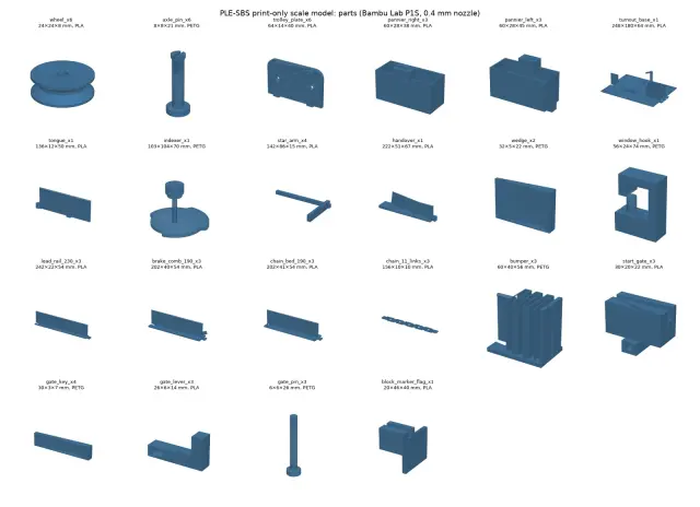
Parts sheet of the print-only scale model: wheels, trolley plates, panniers, turnout base, tongue, indexer, rails, brake combs, chain beds, bumpers
The parts. Twenty-two printed parts, PLA and PETG, generated by one script; the only purchase is the steel wire.
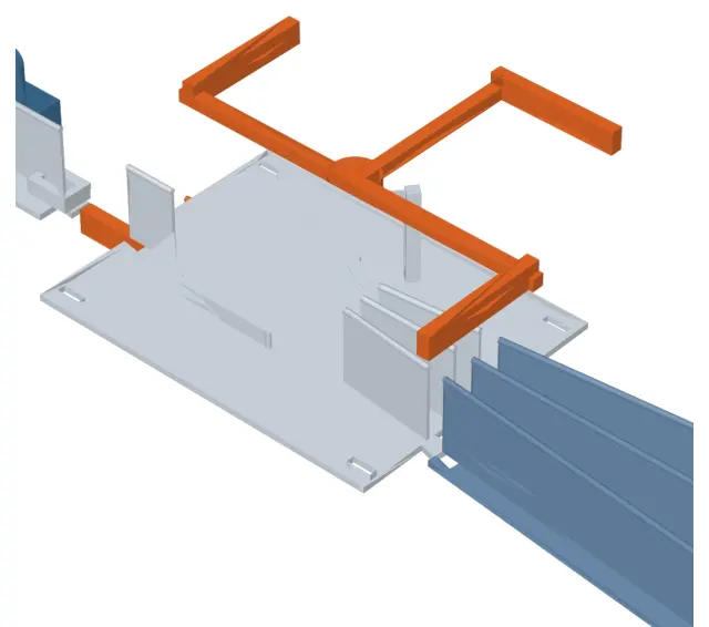
Render of the turnout plate with the self-indexing star and three bay rails
The switch yard at 1:50. The tongue, the four-arm star and the three bays, rendered from the part files.
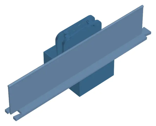
Render of the printed pod: two plates, two wheels and two pannier halves
A pod. Two plates, two V-groove wheels on snap pins, two panniers on dovetails; no screws, bearings or glue.
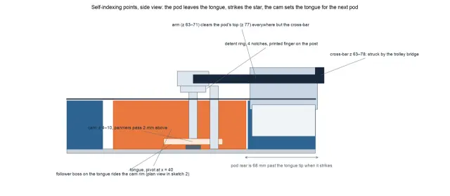
Side-view sketch of the self-indexing points: the pod leaves the tongue, strikes the star, and the cam sets the tongue for the next pod
The mechanism. The pod's top strikes the star; a four-dwell cam on the same shaft sets the tongue for the next pod.
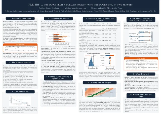
The PLE-SBS research poster, A0 landscape
The poster. A0, from the paper of 10 June 2026. Photographs of the printed model and its timed runs are the next thing to add here.